The TRISO Fuel Revolution
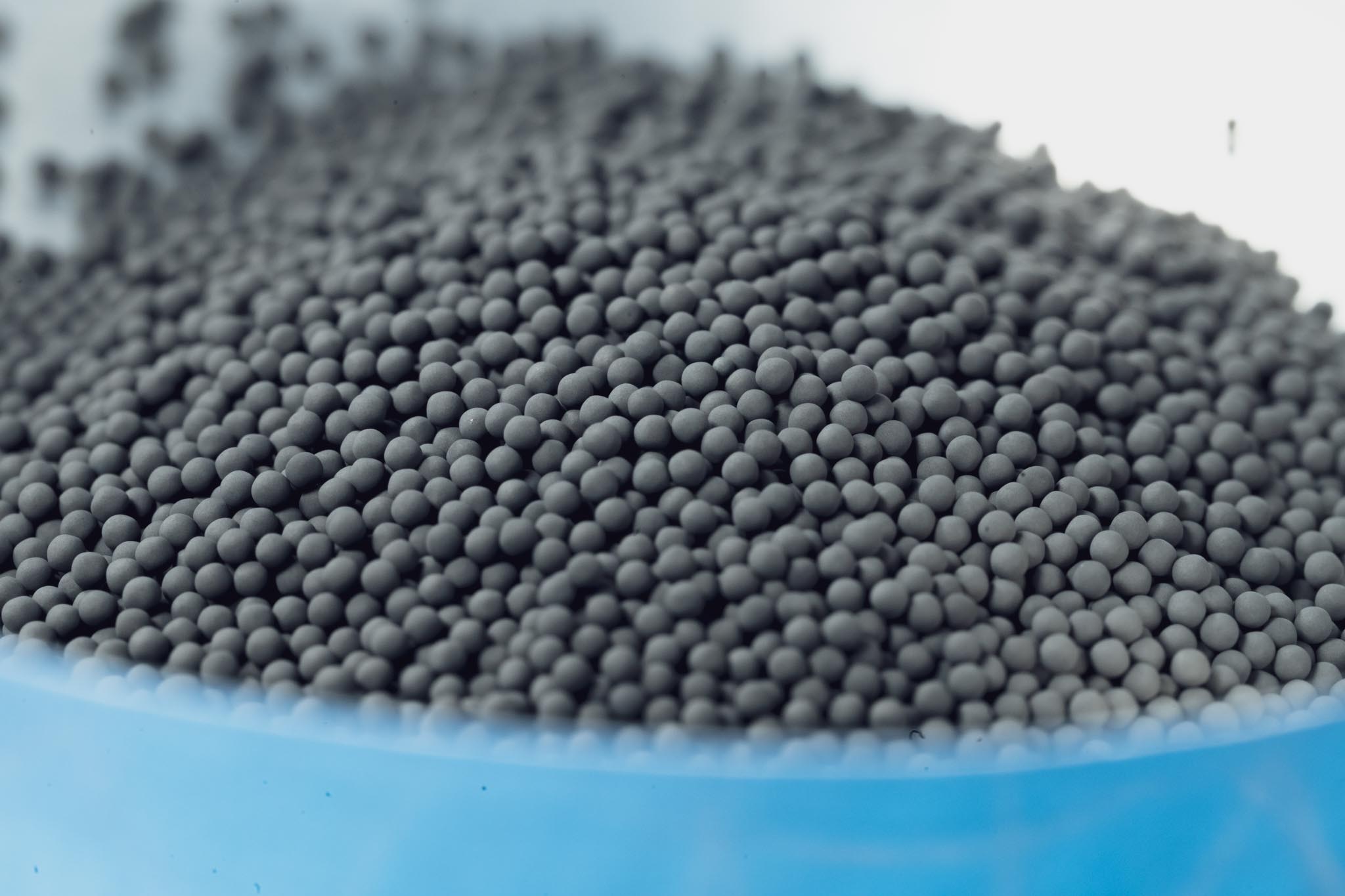
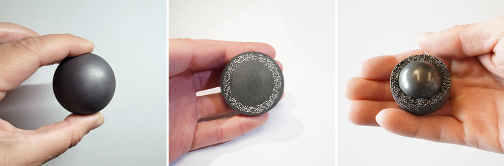
These are TRISO nuclear fuel particles and they look like sesame seeds. The central sphere is a nuclear fuel like Uranium Oxycarbide (UCO), and the shells are made of various ceramics. It gets put into fuel pellets in the shape of cylinders. A single TRISO particle weighs about 1.7 mg, of which 1 mg is Uranium. Its volume is 4.2 microliters. In a state-of-the-art reactor, a single TRISO particle can produce 3.6 kWh of energy, enough to power a house for a few hours. And a typical high temperature gas cooled reactor (HTGR) will contain about 1 billion TRISO particles.
There are more than a dozen reactors being designed to use TRISO fuel. All but three use helium coolant. So it seems that TRISO-fueled reactors will soon be all over the place. This post is aimed at showing people what TRISO particles are, how they work, and why they are different and better than traditional nuclear fuel. My intent is to provide a better resource compared to marketing or articles found online that are minimally researched and have little to no understanding concerning TRISO's technological basis and history.
What is TRISO Particle fuel?
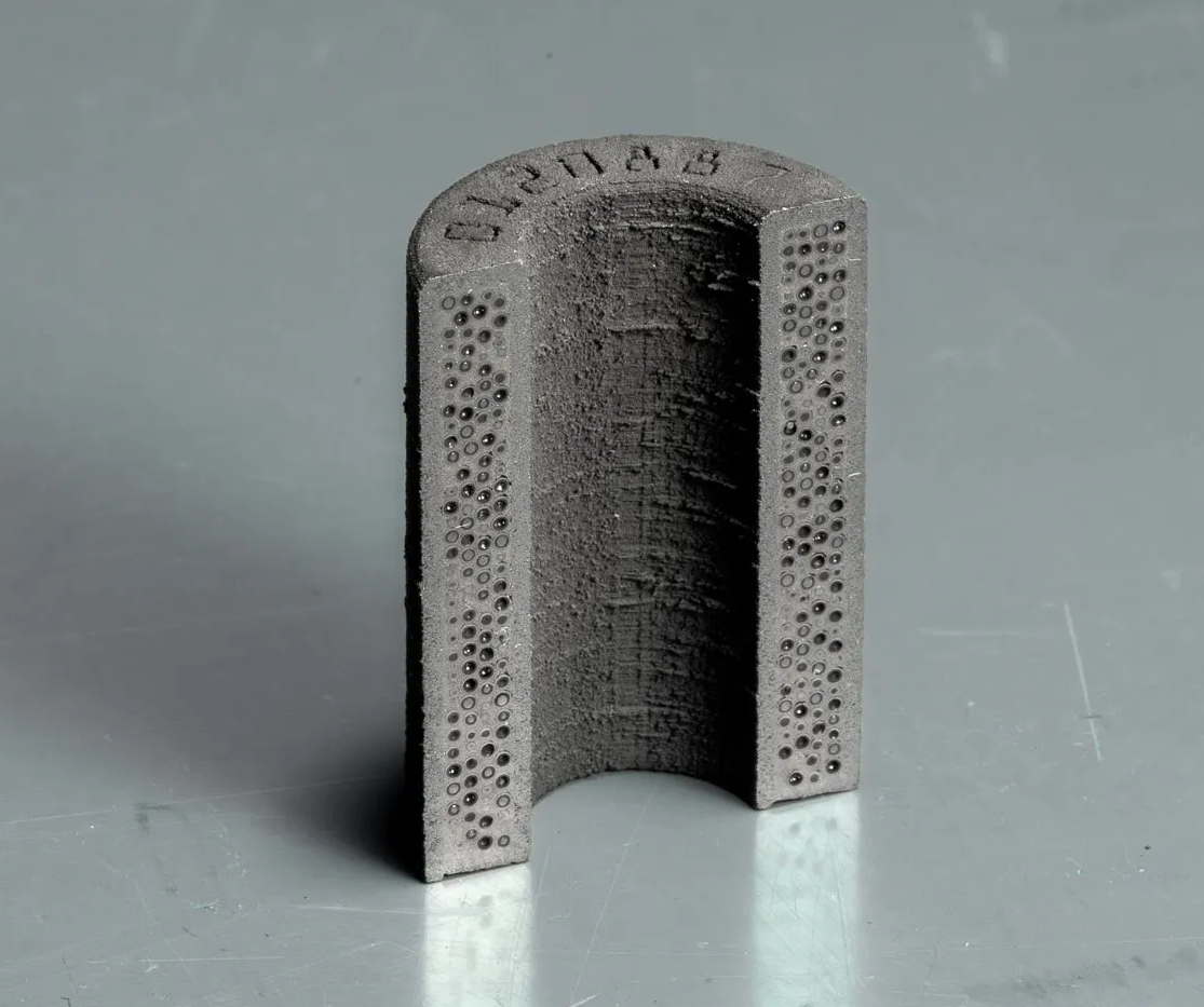
Originally conceived in 1957 1, TRistructural ISOtropic (TRISO) particle fuel consists of fissile Uranium or Thorium fuel kernels measuring 350 to 600 μm across and coated with layers of Pyrolytic Carbon and Silicon Carbide. TRISO particles are the fuel spheres with ceramic layers, while the matrix is the ceramic material that surrounds the TRISO particles to form a consolidated fuel pellet, usually a cylinder, measuring about 1-2 cm in diameter. The matrix is traditionally dense graphite but improved versions use SiC or ZrC.
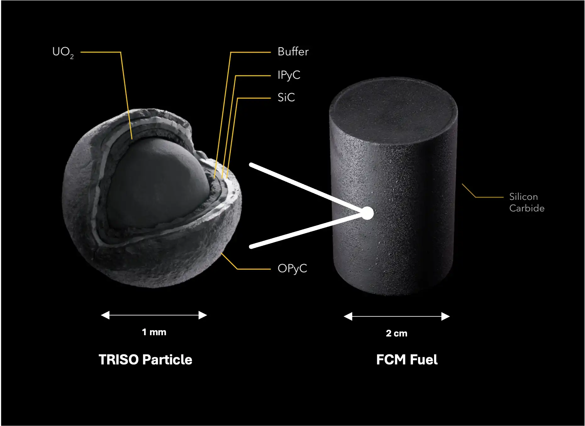
TRISO particle fuel is fundamentally different from conventional fuel which are centimeter-sized pellets of Uranium Dioxide enclosed in Zircaloy tubes. The driving idea behind TRISO particle fuel is to give each 350 to 600 μm sized piece of nuclear fuel its own containment and pressure vessel to enhance the fuel’s ability to contain fission products at very high temperatures and neutron bombardment. The physical basis for miniaturizing the pressure vessel is twofold: fuel subdivision and pressure vessel enhancement.
Compared to normal fuel elements, a TRISO particle contains 5 million times less fissionable mass. Subdividing the nuclear fuel into discrete and self-containing packets eliminates the risk of single point failures in the pressure vessel or fuel cladding. Ordinarily, a single failure in the reactor’s main steel pressure vessel would lead to a nuclear accident. Even a single failure in a conventional fuel cladding results in leakage of fission products into the coolant and the vessel that can result in an unplanned outage or worse. With TRISO, single failures are unlikely, and when they occur, lead to a small radiation release into the fuel matrix where it is likely stopped. The subdivision of fuel into particles is even believed to provide blast resistance as the particles are small and robust enough to remain intact during explosive fractures like a direct missile hit.2
The second advantage to miniaturizing the pressure vessel is the ability to enhance pressure vessel performance through use of thin layered ceramics in a mass-manufactured, seamless, spherical design. Fabrication of millions of particle pressure vessels can be highly standardized and controlled in a mass manufacturing environment with defect rates of less than 1 in 100,000.3 Crucially, the millimeter scale vessel allows the use of highly pure brittle ceramics made through CVD techniques that maintain high strength and stability under high temperature and irradiation and have dual use as low reactivity fission product barriers. Normal reactor pressure vessels are made one at a time and have to be cylindrical, with various welding and joining techniques, multi-cm wall thickness, and cannot be made from ceramics, instead using metals that melt. As the pressure vessel size is reduced, the more efficient spherical geometry can be adopted, and the required wall thickness drops dramatically to the point that a 35 μm SiC layer can indefinitely contain gas pressures in excess of 200 MPa.4 This compares to the main reactor steel pressure vessel which may go as high as 20 MPa or the Zircaloy cladding which can have pressures up to 10s of MPa in limited conditions – temperatures far below what the ceramic pressure vessels can tolerate. As the nuclear fuel fissions, it continues to accumulate fission product gases and this increases the gas pressure that must be contained. If the pressure vessel can handle higher pressures, the fuel can be burned more extensively and safely, which means more efficient use of fuel.
The attractiveness of TRISO-matrix fuel is derived from its ceramics' unusually high thermal conductivity, high fission product retention, and superior corrosion resistance across operating, accident, and storage conditions. This translates into better economic potential and safety for current civilian reactors (higher temperatures, burnups, and power densities with higher safety margins) as well as upcoming microreactors, gas cooled reactors, and molten salt cooled reactors. More extreme performance applications enabled by TRISO-matrix type concepts include nuclear thermal propulsion (NTP) for space, VHTR, Subterrene tunneling, and nuclear ramjets.
How is TRISO fuel made?
The fabrication process is composed of two parts – first, the fabrication of TRISO particles, and second, the fabrication of fuel pellets containing those TRISO particles. The first step is to package Uranium into spherical kernels using the sol-gel process. Uranium oxide is dissolved in nitric acid to make a broth solution of uranyl nitrate. This yellow solution is combined with an organic solution to create a uranium gelation broth used in the sol-gel process. A video was produced by USNC to illustrate the fabrication process.
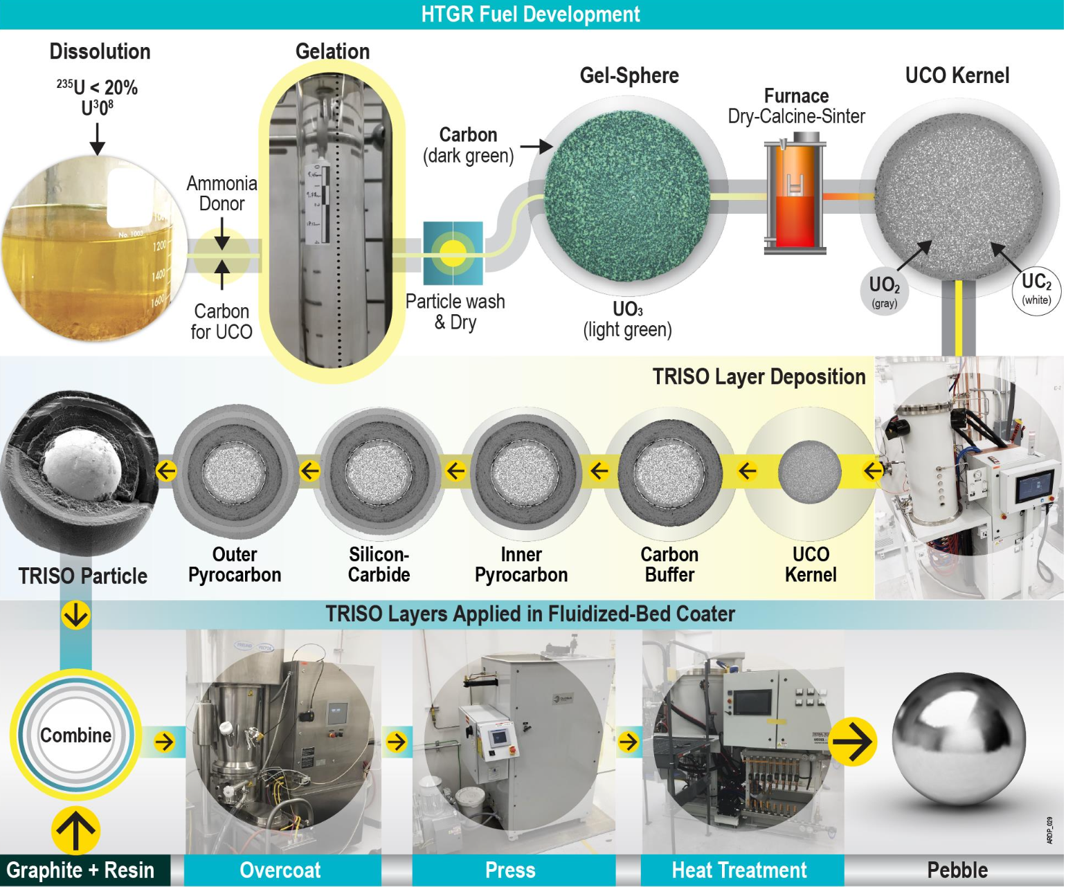
A liquid uranium broth is cooled to low temperatures and dispersed as droplets into an ammonium hydroxide oil bath. The droplets undergo thermally activated reactions that solidify the droplets into soft gel spheres, a few millimeters in diameter. Sphericity is maintained by ensuring the droplets gel before colliding with the solution to form ammonium diuranate kernels. The kernels are washed to remove water and any reaction products.
The kernels are then prepared for a high temperature furnace, to calcine, convert, and sinter mixed uranium trioxide and carbon-bearing particles from the sol-gel process to high density uranium oxycarbide or other types of fuel kernels.
Multiple engineered coatings, each with a specific purpose, are added to the fuel kernel via chemical vapor deposition (CVD) in a fluidized bed, a system designed to batch coat particles through CVD in a continuous process. Following recipes tuned over the last several decades, gases are injected into a hot fluidized chamber which can reach temperatures of up to 1700°C. The gases react to deposit chemicals onto the spheres. Layer order and thickness is optimized to achieve necessary chemical and structural properties and can vary with the type of fissile fuel being used and the required burnup.
The thickness, porosity, grain size, and texture are strictly controlled to achieve the desired performance. SiC and graphite layers offer excellent radiation and temperature tolerance, maintaining their performance characteristics across the intended temperature and irradiation conditions. The melting temperatures of SiC and graphite are about 2800 °C and 3800 °C, respectively. Pyrolytic Carbon (PyC) layers of varying porosity are formed with acetylene or propylene in Ar atmosphere. The SiC layer is formed with methyl trichlorosilane with H2.
One by one, size separation is achieved using roller pins or screens. The rollers are slightly angled so that particles fall through with increasing size. Misshapen or non-spherical particles are sorted using an inclined vibratory plane.
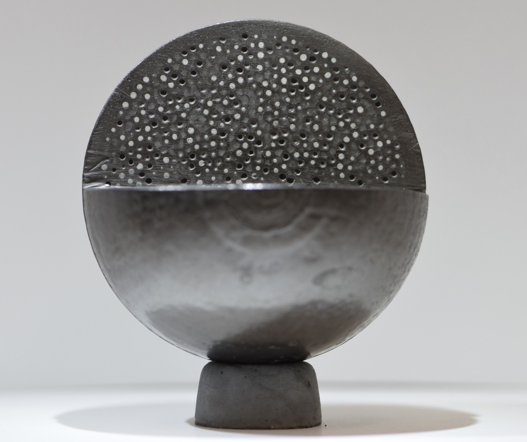
The particles are then embedded in a ceramic matrix: either graphite or silicon carbide (also known as Fully Ceramic Encapsulated Fuel) and pellets can take various shapes including cylinders, annuli, spheres, and hollow spheres.
One HTGR reactor core will have on the order of 100 million (tiny reactors) to 5 billion particles per core loading. A typical Micro Modular Reactor core would contain 1 billion standard TRISO particles, which hold about 700 kg of Uranium oxide or 900 kg of Uranium Nitride (quite a bit denser). The TRISO particles themselves would weigh about 3600 kg. Assuming 10% Uranium enrichment and moderately optimistic fab cost estimates, the cost of such a core would be on the order of 21 $M or 15,000 $/kg of heavy metal. After considering a standard balance of plant and state-of-the-art fuel burnup of 150 MWd/kg, the fuel cost would contribute about 3.5 cents/kWhr of delivered electrical energy (see my thesis for how to estimate these costs).
TRISO Particle Design Motivation and Layer Roles
Challenges
The TRISO particle is deeply engineered to address the challenges associated with burning nuclear fuel. Significant effort and possibly hundreds of engineer lives have gone into the detailed analysis and specification of the TRISO layers—their dimensions and material characteristics at the atomic, micro, and macro scales. The primary challenges to address are:
- Swelling and cracking of the UO2 or other nuclear fuel. This is called radiation-induced swelling and fragmentation and can result in significant volume changes of around 30%.
- Release of fission gases which can increase the pressure substantially in the range of 40-100 MPa. Besides high pressure, many of the fission gases are also mobile, able to diffuse through most materials.
- High temperatures in the range of 500-2000 °C. The fuel is generating a lot of heat and the temperatures will be high. The materials must maintain their properties across these high temperatures.
- Radiation damage on the materials significantly degrades their properties. This can include reduced thermal conductivity, swelling, reduced strength, embrittlement, reduced fission product retention etc.
- High thermal throughput from the fuel to the coolant. The layers must allow the heat to pass through to the fuel without getting too hot.
1. Porous Pyrolytic Carbon
The first coating deals with Challenge 1. It is a porous pyrolytic carbon (PyC) buffer layer (Buffer) that acts as a gas chamber for fission product gases and provides sacrificial volume to absorb fission product recoils and any swelling from the fuel kernel. PyC is used for its high conductivity at high temperatures, very low thermal expansion, and chemical stability. Higher porosity is achieved by increasing deposition rate which also increases isotropy. Excessive anisotropies can lead to stress concentrations and eventually particle failure.
2. Dense Inner Pyrolytic Carbon
A second but denser inner PyC (IPyC) layer is added to protect the fuel kernel from the subsequent processing steps. In particular, the SiC deposition involves hydrochloric acid products which can damage the layers underneath. The PyC has maximum density to prevent diffusion of heavy metal fission products like Palladium that can attack SiC.
3. Silicon Carbide
SiC solves Challenge 2. The Silicon Carbide layer acts as the pressure vessel and diffusion barrier for the fission product gases. Microstructurally, smaller equiaxed grains are desired as it lowers diffusion of fission products. These are achieved by using lower temperatures during deposition.5
4. Dense Outer Pyrolytic Carbon
A final outer PyC (OPyC) layer protects the SiC from further processing steps and provides a compliant layer between the SiC and the matrix that binds the particles into a pellet. The interaction between the outer and inner PyC layers, which shrink during irradiation, provides compressive stress to the Silicon Carbide layer. This means that the SiC starts in compressive stress and transitions to tensile stress as the fission gas pressure increases.6
5. Matrix or Filler
The pellet matrix, or inter-particle filler material, is ordinarily sintered graphite but can also be sintered SiC as in the FCM fuel.7 This enhances fission product retention and structural stability of the fuel form.
Challenges 3 and 4 are met because the SiC and graphite layers offer excellent radiation and temperature tolerance, maintaining their performance characteristics across the intended temperature and irradiation conditions. The melting temperatures of SiC and graphite are about 2800 °C and 3800 °C, respectively. Both ceramics have good and resilient thermal conductivities, allowing the fuel form to deal with Challenge 5.
Physical Properties of SiC
The key to TRISO’s performance is the β Silicon Carbide layer which possesses the right mix of properties and resilience over the encountered conditions. As shown in Figure 1, materials down selection for nuclear fuels involves minimizing cross sections and various trades on thermal, structural, and chemical properties.8 Depending on the particular reactor type, the materials selection for bulk materials (i.e. significant volumes) is roughly limited to Zirconium alloys and various ceramics including SiC, ZrC, and graphite. There are actually a few ceramics with comparable performance including β-Si3N4, SiAlON, AlN, Al2O3, ZrC, and TiC. However, SiC leverages its good enough properties with the most data, qualification, and established recipes for its manufacture at moderately low temperatures.9
Neutronically benign
From a neutronics perspective, silicon and carbon atoms have small enough cross section for thermal neutrons to not interfere with fission reactions.
High temperature capability
β SiC is the allotrope with a cubic crystal and sp3 hybridization. Strong covalent and somewhat ionic bonding give β SiC nearly best-in-class thermal, structural, and chemical properties in the context of Figure 1. It has a melting temperature on order of 2800°C, low thermal expansion, high thermal conductivity, high strength, and is largely chemically inert.
Fission product barrier
It has negligible diffusion for fission gases in the temperature ranges of interest, even along grain boundaries, for most fission products including Helium gas.10 When incorporated into the TRISO particle, the fission product diffusion through SiC has been measured to be excellent up to 1400 K with Ag, Eu, Kr posing limited risks at higher temperatures.
Extreme irradiation tolerance
But SiC’s most significant advantage is its behavior under extreme irradiation and temperature. While most materials swell, transmute, and deteriorate to the point of crumbling, irradiated SiC converges to a quite acceptable equilibrium, at least when it is highly crystalline, pure, and cubic. The swelling is indicative of the overall degradation and it should be noted that elastic modulus and thermal conductivity trend with the swelling and also equilibrate at acceptable values.
Swelling occurs when neutron irradiation creates interstitials and vacancies, with the interstitials usually migrating faster towards dislocations, which leaves excess vacancies to form voids and cause the material to swell. The time rate of swelling is determined by the flux of vacancies compared to the flux of interstitials, simply as the difference between the fluxes ɸ.11 In SiC at temperatures between 423 K and 1273 K, defect formation is low due to thermal recombination, and the interstitial flux is high enough to match the vacancy flux so that the defects annihilate and the swelling stops.12 13 Swelling behavior has been measured up to 1600 °C and reveals 3 regimes. The temperatures of interest for nuclear fuel are between 400 to 1000 °C for which SiC shows saturated swelling behavior.10
Suppliers
New TRISO suppliers are forming in the US, Europe, South Africa, Middle East, and Asia. It's just too easy to make TRISO and the expertise is available. But as is often the case in the nuclear world, the quietest players are also the most productive. As of 2025, China, Japan, and US's BWXT are the clear leaders producing TRISO fuel in significant quantities.
China National Nuclear Corp (CNNC)
CNNC is the current world leader in large scale production of TRISO particles at their Baotou facilities in Inner Mongolia. The facility has capacity to supply more than ten HTR-PMs. Besides providing fuel for the High Temperature Gas Cooled Reactors in China and abroad, CNNC plans to use TRISO in their thorium-fueled molten salt cooled program. They currently supply 2 HTR-PM reactors operating at 1% capacity factor since 2021 - roughly 300,000 spherical pebbles per year. The Chinese licensed reactor and fuel technology from the dying German HTGR efforts in the 80s and 90s. The factory is based on a trial production line developed by INET at Tsinghua University to produce 100,000 spherical fuel pebbles per year. Fuel production at Baotou started in March 2016.
Japan Atomic Energy Agency (JAEA)
JAEA operates a production line to supply the HTTR test reactor which was restarted in 2021.
BWXT
Production capabilities are being ramped up to supply the DOD Pele Program for Army transportable reactors, NASA's Lunar Surface Fission Power program, Jetson, and the BANR HTGR project. Some of these projects might not even use TRISO, favoring more fuel dense UO2 pellets, but that's unclear.
TRISO-X
TRISO-X, a subsidiary of X-Energy, should begin work on the TX-1 fuel factory in Tennessee to provide fuel for their various pebble bed projects. TRISO-X has been pursuing TRISO fuels since 2015 with a DOE grant of $40M and delivering lab-scale TRISO samples out of a DOE facility and more recently a lab-scale site within Centrus TMC. Their full scale fabrication facility is at the planning stage, but is heavily backed by Amazon and the DOE Advanced Reactor Demonstration Program.
Kairos Power
Kairos Power has a production line (Low-Enriched Fuel Fabrication Facility) in the works in partnership with Los Alamos National Laboratory. The fuel will be needed pretty soon for their Fluoride Salt Cooled reactor. Lack of fuel will probably delay their first demonstration to 2029 or later.
Ultra Safe Nuclear Corporation
Ultra Safe Nuclear has factory plans in Washington state in partnership with Framatome. They have a pilot facility in Knoxville, Tennessee. Funnily enough, the site is right next to TRISO-X TX-1 plot of land and the KAIROS reactor demo site, all of which is on brownfield land at the K-25 gaseous diffusion enrichment plant. Ultra Safe Nuclear is the only supplier to have improved on the original TRISO particle fuel form by encapsulating TRISO particles in Silicon Carbide rather than graphite, which has several advantages. Ultra Safe also aimed to supply TRISO particle or TRISO-like fuels for Nuclear Thermal Propulsion.
Ultra Safe Nuclear was bankrupted in Fall of 2024 and the fuel business was bought and rebranded as Standard Nuclear. All the important licensed patents have reverted back to UT-Battelle - a nice relief to other players.
Lingering issues with TRISO
TRISO fuel is a nearly perfect fuel form, but there are issues of course, even ignoring the near-term cost barriers. A major problem is the large reactor size required for TRISO fuel. By volume, a TRISO particle is less than 10% uranium, which means lots of wasted volume in the core. This requires very large cores or exotic moderators for a good neutron economy and fuel burnup. You could have fleet operations of small reactors with fresh fuel and low burnup of the fuel, followed by a complete burnup of that fuel in a large centralized reactor. That's a new idea that needs to overcome challenges with the transport of used fuel to be used in another reactor—which I don't believe has ever been done before.
TRISO particle costs
The cost of TRISO fuel is often brought up as a key limiting factor to adoption. This is a typical short-sighted observation by armchair quibblers and the mentally challenged. The same people would predict decades of stagnant photovoltaic and battery costs. Worldwide production of TRISO is currently less than 2 tons of heavy metal. Compare that to the 27 tons of enriched heavy metal required per standard large reactor (1 gigawatt electrical output) and the worldwide production of 10,000 tons per year uranium (5% enriched). We haven't even tried producing TRISO at any meaningful scale.
Today, you'll probably get quoted a TRISO fabrication cost on the order of 20 to 45 thousand dollars per kg of heavy metal (UO2). Crazy high compared to a few thousand at most for regular fuel pellets. Yes, it's expensive to make a few kilograms of TRISO particles with custom-designed furnaces and fluidized beds in tiny facilities run by scientists and funded by the US government who will pay just about anything for anything. In a high production and competitive marketplace, the cost of TRISO fuel will be the same as the cost of the contained uranium - like the packaging on any good and service. It's too easy to fabricate and everyone can do it - it's old tech. The margins will be razor thin.
TRISO won't even have to pay for itself. But it reduces costs in other parts of the nuclear reactor. Compared to conventional fuel, the benefits of TRISO include doing away with expensive Zircaloy claddings that fail in anything but the design conditions, eliminating spent fuel pools and reducing the spent fuel mass, true zero emergency planning zones, higher temperature and higher efficiency cycles, etc.
TRISO fabrication challenges
While many fabricators claim to have reliably manufactured TRISO particles and fuel pellets, challenges remain. First, no one has really irradiated the fuel to its maximum burnup in statistically meaningful quantities. Qualification tests are done on at most a few hundred fuel pellet samples and those are usually cherry-picked for the best looking ones. The entire safety case of a TRISO fueled reactor rests on the quality control of billions of tiny particles with defective particles numbering 1 in 100,000. How can that quality control be assured over time?
Another fabrication challenge is the exotic pellet forms some are developing including spheres with internal graphite cores or Silicon Carbide matrix - the so-called Fully Ceramic Micro-encapsulated FCM fuel invented by Francesco Venneri (my pops) and company. Compaction of TRISO particles into fuel pellets can lead to inadvertent damage to the particles which is difficult to detect until the fuel starts leaking fission gases in the reactor. In the same compaction step, the distance between particles is difficult to control which can lead to overheating or stress concentration during fabrication or operations and premature fuel failure. New methods for SiC matrix encapsulation try to get around the compaction and high pressure sintering (or spark plasma sintering) step and utilize ceramic additive printers from Desktop Metal that are notoriously unreliable and have not achieved scaled production for any industrial product let alone nuclear fuel.
The Future of TRISO is Bright
There are dozens of advanced nuclear reactors at various stages of development, and about a dozen aim to use TRISO-based nuclear fuels. For regulators and the public, the demonstration of these reactors and fuels will provide a useful comparison relative to the metallic, molten, and ordinary fuel reactors that are also in development. We may finally have useful comparisons.
| Name | Full Name | Vendor | Status | Enrichment (%) |
|---|---|---|---|---|
| HTR-PM | High Temperature Reactor Pebble Module | DBD Limited / INET | Operating | 9.08 |
| HTTR | High Temperature Test Reactor | JAEA | Operating | 9 |
| PELE | BWXT Advanced Nuclear Reactor for DoD PELE | BWXT | Stated 2024+ completion | 19.75 |
| BANR | BWXT Advanced Nuclear Reactor | BWXT | Concept | 19.75 |
| MMR | Micro Modular Reactor | Ultra Safe Nuclear | Stated 2026 completion | 9.9 |
| FHR | Fluoride Salt-cooled High-Temperature Reactor | Kairos Power | Stated late 2020s | 19.75 |
| U-Battery | U-Battery HTGR | U-Battery / Urenco | Stated late 2020s | 19.75 |
| PYLON | Pylon | Ultra Safe Nuclear | Stated late 2020s completion | 19.75 |
| Kaleidos | Kaleidos | Radiant Nuclear | Stated 2026 initial core tests | 19.75 |
| eVinci | eVinci heat-pipe micro reactor | Westinghouse | Stated 2028 completion | 19.75 |
| Xe-100 | Xe-100 | X-Energy | Stated 2030 completion | 15.5 |
| EM2 | Energy Multiplier Module | General Atomics | Concept | 14.5 |
| MGHTR | Modular Integrated Gas-Cooled High Temperature Reactor | Boston Atomics | Concept | 19.75 |
| R1 | R1 Microreactor | Antares Industries | Concept | 19.75 |
| JimmyGen | Jimmy thermal generator | Jimmy Energy | Concept | 19.75 |
| Ward Zero | Ward Zero prototype HTGR | Valar Atomics | Concept | 19.75 |
| ZEUS | ZEUS Microreactor | Nano Nuclear Energy | Concept | 19.75 |
Footnotes
-
K. Verfondern, H. Nabielek & J. M. Kendall. Coated particle fuel for HTGCR.pdf. Nuclear engineering and technology 39, 603 (2007). ↩
-
PELE PROGRAM PHASE I. ↩
-
Hales et al., “Multidimensional Multiphysics Simulation of TRISO Particle Fuel.” ↩
-
Petti et al., “Key Differences in the Fabrication, Irradiation and High Temperature Accident Testing of US and German TRISO-Coated Particle Fuel, and Their Implications on Fuel Performance.” ↩
-
Konings and Verfondern, TRISO Fuel Performance Modeling and Simulation. ↩
-
Mehner et al., “Spherical Fuel Elements for Advanced HTR Manufacture and Qualification by Irradiation Testing.”; Heit et al., “Status of Qualification of High-Temperature Reactor Fuel Element Spheres.”; Sawa, TRISO Fuel Production; Date and Phase, “VDR Focus Area 04 MMR-REM Fuel Design and Qualification.” ↩
-
Hosemann et al., “Materials Selection for Nuclear Applications: Challenges and Opportunities”; Azevedo, “Selection of Fuel Cladding Material for Nuclear Fission Reactors.” ↩
-
Snead et al., “Handbook of SiC Properties for Fuel Performance Modeling.” ↩ ↩2
-
Katoh et al., “Microstructural Development in Cubic Silicon Carbide during Irradiation at Elevated Temperatures.” ↩
-
Katoh et al., “Stability of SiC and Its Composites at High Neutron Fluence.” ↩