Time-variable Observation

Measuring time-varying signals with a single 2D image
Semiconductor sensors have extended the range of human's ability to sense photons from a mere 400-700 nm to 200-3000 nm. We can measure single photons, and we can measure them with increasingly higher spatial resolution. However, we have more difficulty measuring photons' arrival times. Mostly, we just collect photons in pixels over an exposure and integrate the result. We can take multiple exposures over time, and these are time stamped. But the arrival times of photons within an exposure are not measurable using current techniques. The standard approach to get some temporal resolution is to simply take more exposures with shorter integration periods but this has issues with data throughout and signal to noise.
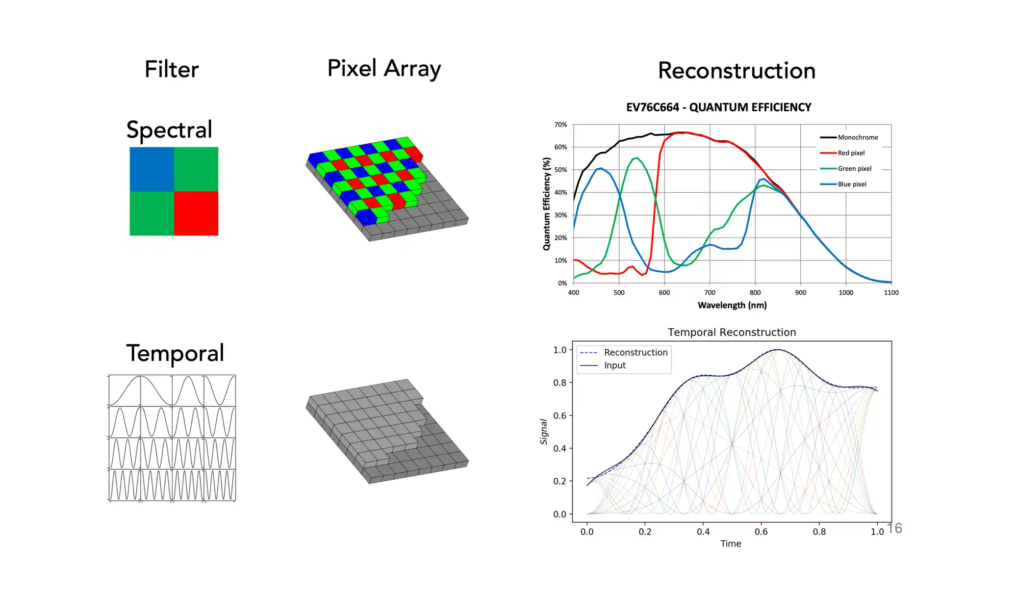
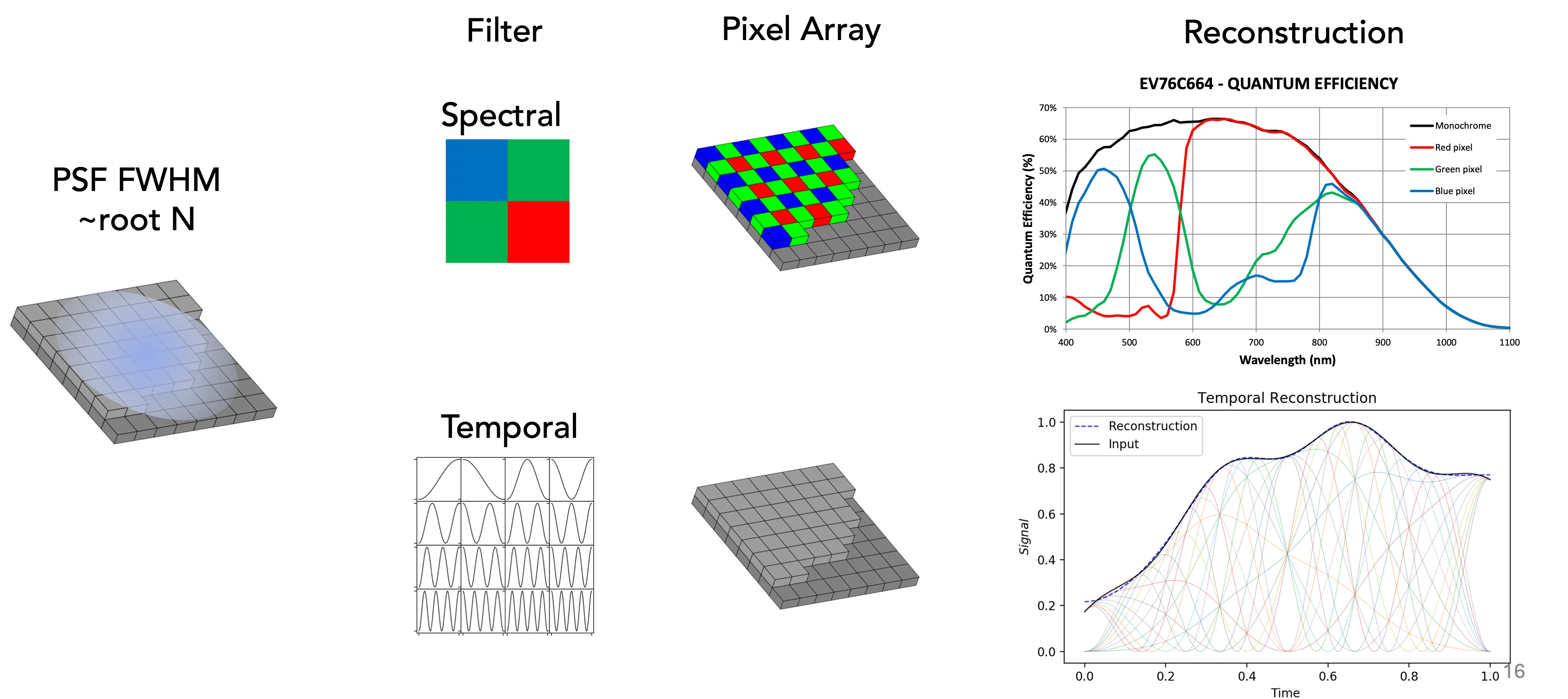
The concept is to measure the light from the same star with a group of pixels, each having a different temporal exposure modulation. In the same way that an RGB array acts as spectral separator, a modulation array acts as a separator of temporal information that occurs during the integration period. Instead of red, green, and blue pixels, we have different exposure modulations for each pixel. This technique allows the user to find temporal behavior during the exposure itself by multiplexing time information on spatial pixels. Beyond stars, the same technique can be used to achieve higher frame rates in optical cameras, thereby overcoming limitations from sensor readout and shutter speed.
This document accompanies a presentation given for the Rice University Astronomy Seminar and describes a method for subtracting ambient light that can be generalized via a Gram system to measure time variability of optical signals using a single image exposure. As the RGB Bayer filter projects the wavelength spectrum onto a wavelength bandpass basis, the temporal filter herein described projects the temporal function of a signal onto temporal basis using an array of optical modulators. Reconstruction of the original optical signal can then be achieved by solving a Gram system.
Hardware Approaches

Liquid Crystal Display
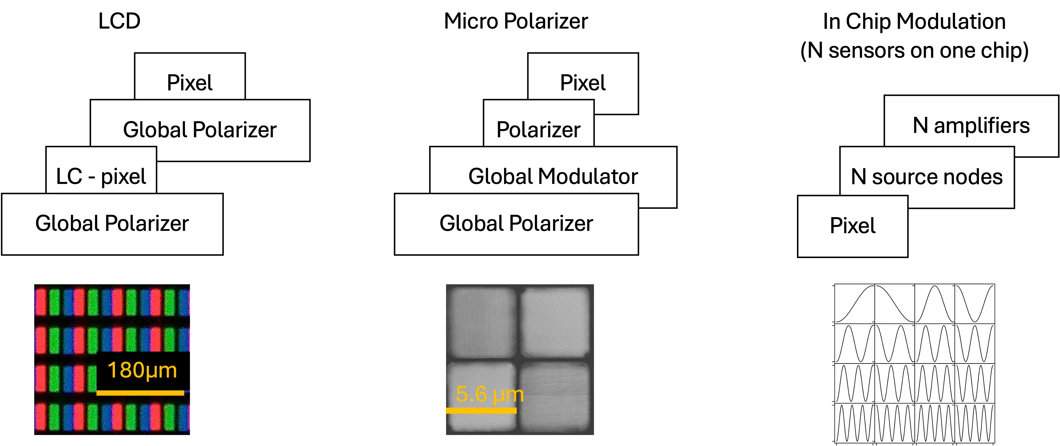
The ideal solution would be a programmable modulation for each pixel. With current state of the art LCD technology, it is possible to place an individually programmable modulator in front of each pixel for pixel pitches as small as 27.5 microns. This means the modulation function and the number of modulators can be chosen on the fly or perhaps in response to previous measurements. Because they are used for RGB displays and have undergone decades of industry research, LCDs are optically broadband and highly robust over varied operating conditions. Perhaps the only drawback of the LCD is a standard refresh rate of at most 120 Hz.
An extra benefit of an LCD placed at the focal plane is its dual use as a locally adaptive shutter to enhance the Dynamic range of the sensor. Dynamic range problems have arisen by which increasingly larger telescopes are saturating on dim reference stars. Saturation of stars can lead to banding and global offsets for the entire chip leading to errors that are difficult to correct. It is then desired to attenuate the brightest objects without attenuating the dim objects. The LCD can be used to variably attenuate all stars to achieve non saturating measurements. In practice, a test image would be produced with no attenuation that identifies the brightest objects. The exposure over the brightest objects in the array can then be adjusted by dimming pixels only over those objects.

Micro Patterned Analyzers
If pixel pitch becomes a limiting factor for an LCD approach, a polarizer grid can be placed directly on the silicon sensor, either as part of the 1st metal layer during sensor fabrication, or as an added ion beam etched wire grid polarizer. The superpixel would be composed of 4 states: 0, 45, 90, and 135 allowing for a complete identification of the Stokes’s parameters. There are several manufacturers for pixellated or micro patterned polarizer grids that have achieved optical wire grid polarizers as small as 5.6 microns. On top of the grid, a global polarization rotating mechanism rotates the polarized input beam through 180 degrees. When analyzed by the 4 polarizer states, this yields 4 distinct modulation functions. The polarization can be rotated globally by a single ITO coated liquid crystal, a mechanically rotating half-waveplate, or a Pockels Cell.
Chip modulation
An emerging practice in High Dynamic Range sensors is to use dual simultaneous exposures of different lengths to effectively increase the dynamic range of the sensor. Even rows are exposed at one exposure length and odd rows at another. This is done by using multiple transfer gates and sense nodes. A similar approach can be taken to incorporate different modulations for N rows in the final read out.